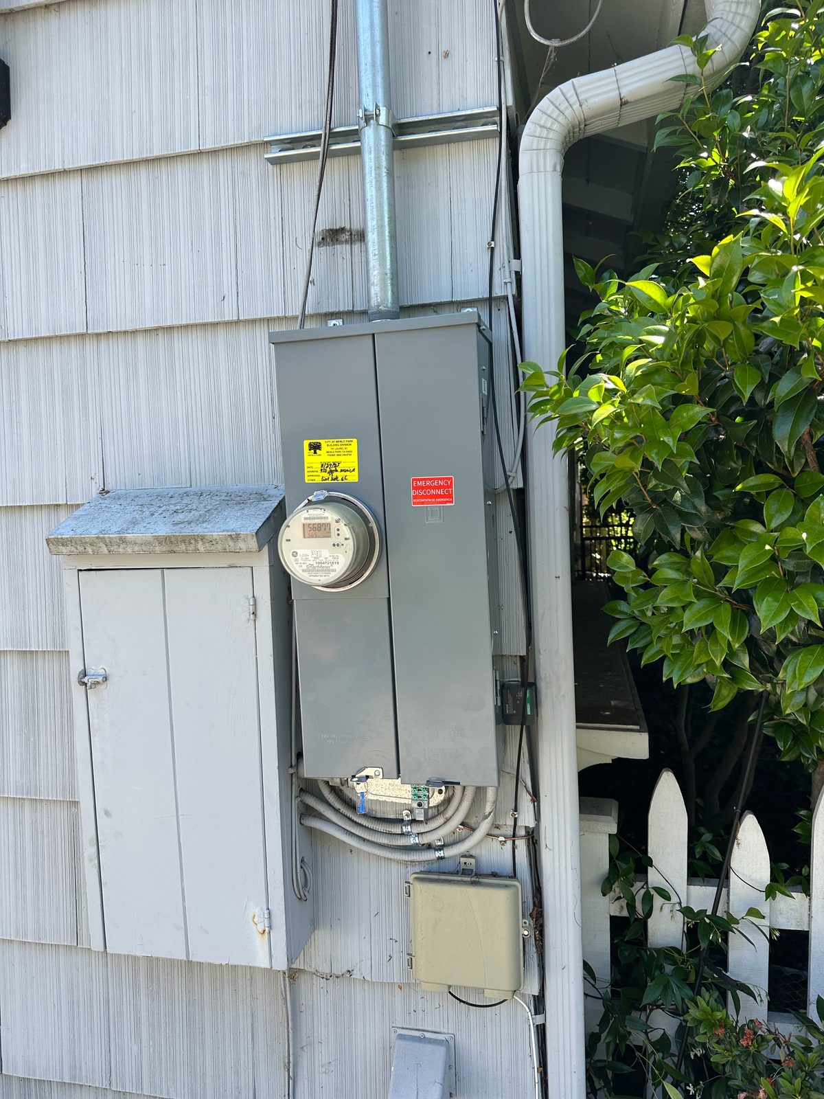
Estimate only. This is a simplified textbook method. A licensed electrician or engineer must verify the available fault current before equipment is chosen, labeled or approved. When the utility gives you a number, use it.
Run the numbers
Available fault current (symmetrical amps)
Compared with common interrupting ratings
“Above the estimate” means that rating is higher than the estimated current. It doesn’t make equipment acceptable by itself: series ratings, motor loads and the actual equipment labels all matter.
How we figured this
Prefer the full contact form? Open it with this filled in.
What the code asks for, in plain English
Our own summary, not the code text. Check the edition your city or county enforces.
- Interrupting rating (110.9)A breaker or fuse meant to stop fault current needs a rating high enough for the current available at its line terminals at the system voltage.
- Short-circuit ratings and coordination (110.10)The circuit’s impedance, the equipment’s short-circuit current ratings and the protective devices need to work together so a fault is cleared without extensive damage.
- Field marking (110.24)Service equipment, other than at dwelling units, gets a durable field label showing the available fault current and the date it was calculated, and the calculation has to be documented. When later changes affect it, it’s checked again and the label is updated. Certain industrial sites with qualified maintenance staff are exempt (EC&M, Electrical Contractor).
Ask PG&E first. PG&E will provide the maximum available fault current at a service location in an AIC letter, requested through your project’s PG&E job owner. Early requests are based on conservative, worst-case assumptions (PG&E Greenbook). When you have their number, use it.
How the point-to-point method works
- Full-load amps. Three-phase: kVA × 1,000 ÷ (volts line-to-line × 1.732). Single-phase: kVA × 1,000 ÷ volts line-to-line.
- Multiplier. 100 ÷ %Z. Listed transformers 25 kVA and up can be 10% under nameplate impedance, so the worst case uses 0.9 × %Z.
- Fault current at the transformer. Full-load amps × multiplier, assuming the utility can supply unlimited current. If the primary fault current is known, the handbook reduces this with its own f and M step.
- f factor for each run. Three-phase: 1.732 × length × starting amps ÷ (C × parallel sets × volts). Single-phase: the same with 2 in place of 1.732; line-to-neutral uses 120 V.
- M. 1 ÷ (1 + f).
- Fault current at the end of the run. Starting amps × M. Repeat for the next run. Motor contribution, if used, is added at every point.
Method and C values: Bussmann, Eaton, Mike Holt. Utility voltage can also run up to 10% high, which raises fault current; this calculator doesn’t add that.
Checked against published worked examples
We ran the handbook examples through the calculator. Every one matches within rounding.
| Example | Published | Calculator |
|---|---|---|
| Bussmann System A: 1,500 kVA, 480 V, 3.5%Z, transformer terminals | 51,540 A | 51,551 A |
| System A, fault X1: 25 ft, six sets of 500 kcmil Cu in steel (f 0.0349) | 49,803 A; 57,019 A with motors | 49,810 A; 57,026 A |
| System A, fault X2: 50 ft, one 500 kcmil Cu in steel (f 0.4050) | 35,445 A; 42,661 A with motors | 35,450 A; 42,666 A |
| Bussmann System B: 1,000 kVA, 30 ft four sets of 500 kcmil in PVC, then 20 ft two sets of 2/0 | 33,215 A; 30,059 A | 33,211 A; 30,058 A |
| System B, second transformer: 225 kVA, 208 V, 1.2%Z, primary fault known | 29,731 A | 29,736 A |
| Bussmann single-phase: 75 kVA, 120/240 V, 1.40%Z, 25 ft 500 kcmil in steel | 18,453 A L-L; 20,555 A L-N | 18,453 A; 20,556 A |
| Galco (System A reproduced): terminals, X1, X2 | 51,551 / 49,810 / 35,450 A | 51,551 / 49,810 / 35,450 A |
What this calculator doesn’t do
- A full short-circuit studyIt ignores X/R ratio and asymmetry, arcing current, generators, UPS units, network systems and parallel transformers. It isn’t an arc flash study.
- Line-to-line faults on three-phase systemsThree-phase results are bolted three-phase faults, the highest case used for ratings.
- Busway and cable assembliesOnly single conductors in conduit, from the published table.
How IES helps
- We check it properlyWe get the utility’s number, read the equipment labels and confirm the ratings fit.
- Service and panel work, start to finishPermits, inspection, and the PG&E coordination.
- Free estimatesCall (530) 401-7419, answered 24/7, or send your numbers below.
Sizing the service itself? Try the Load Calculator or the quick Panel-Size Helper.
Common questions
What is available fault current?
It’s the most current that could flow at a point in the system if the wires were shorted together right there. It’s highest at the transformer and drops as you go farther down the wires, because the wire adds resistance.
Why does it matter?
Breakers, fuses and panels are only tested to safely stop so much current. If the available fault current is more than a device’s rating, it may not be able to clear a short safely. The code asks that ratings be high enough for the current available where the equipment is installed.
What do the f and M numbers mean?
They are the two steps of the point-to-point method. The f factor compares the wire’s impedance with the current at the start of the run. The multiplier M is 1 divided by (1 + f). Multiply the starting current by M to get the current at the end of the run.
Should I use the utility’s number instead?
Yes, when you can get it. In our area PG&E will provide the maximum available fault current at a service location in an AIC letter, through the job owner on your project. Enter that number with the “utility gave me the fault current” choice and work downstream from there.
Why is the line-to-neutral current higher at a home transformer?
For a single-phase 120/240 V transformer with a center tap, the published method estimates the line-to-neutral fault current at the terminals as 1.5 times the line-to-line value. It drops faster along the wire, so a little way out it’s often lower than the line-to-line value.
Is this a short-circuit study?
No. It’s a simplified estimate that ignores things like X/R ratio, asymmetry, arcing current and device coordination. A licensed electrician or engineer has to verify the actual available fault current before equipment is chosen or marked.
Send your numbers for a free estimate
Free estimates, no pressure. Tell us a little about the job and we’ll get back to you. Or call (530) 401-7419, answered 24/7.
Sources
- Cooper Bussmann: A Simple Approach to Short-Circuit Calculations (point-to-point method, System A and B examples, single-phase examples, C value table) electrical-engineering-portal.com
- Eaton Bussmann: Basic Point-to-Point Calculation Procedure and C values for conductors (current edition) www.eaton.com
- Eaton Bussmann: Short-Circuit Current Calculations (SPD handbook section) www.eaton.com
- Mike Holt Enterprises: Bussmann Electrical Plan Review, point-to-point method and C value tables www.mikeholt.com
- Mike Holt (EC&M), reprinted by the City of Madison Heights, MI: Available Short-Circuit Current www.madisonheightsmi.gov
- Galco: Available fault current calculator, point-to-point method (reproduces the Bussmann System A example) www.galco.com
- PG&E Greenbook (TD-7001M), 2026: Amp Interruption Capacity (AIC/SCI) letter www.pge.com
- EC&M Code Q&A: field marking equipment with available fault current (NEC 110.24) www.ecmweb.com
- Electrical Contractor: General installation requirements, 110.24 and its link to 110.9 and 110.10 www.ecmag.com
The method, C values, examples and code notes checked against the sources above in November 2026. Sources are listed for reference only; we don’t sell or endorse any brand.